Call Us
+86-18072289720
- All
- Product Name
- Product Keyword
- Product Model
- Product Summary
- Product Description
- Multi Field Search

Views: 0 Author: Site Editor Publish Time: 2026-10-31 Origin: Site

Transitioning from light-duty commercial air systems to industrial-grade infrastructure requires a critical evaluation of air demand, duty cycles, and energy efficiency. Facilities generating fluctuating but high-volume air demands often face a difficult choice. They either over-invest in continuous-duty machines or under-invest in inadequate twin-cylinder models. These missteps inevitably lead to premature equipment wear or massive energy waste. We provide a transparent, specification-driven framework to help evaluate whether a 4 cylinder compressor aligns exactly to your operational requirements and facility constraints.
You will learn how distinct cylinder configurations impact thermal dynamics and mechanical longevity. We also explore ideal industrial applications to see where these machines perform best. Finally, we compare reciprocating models against rotary screw alternatives and outline critical implementation steps. By understanding these core engineering mechanics, you can confidently specify an air system built for heavy bursts of pneumatic demand.
The physical arrangement of cylinders directly dictates how well a pump manages heat and vibration. Manufacturers typically cast a 4 cylinder compressor in a V or W configuration. A V-configuration places two cylinders on each side of the crankcase. This design exposes maximum surface area to the cooling airflow generated by the flywheel fan. A W-configuration spreads four cylinders across three or four banks. It achieves similar thermal dissipation while keeping the overall footprint relatively compact.
Inline configurations stack all cylinders in a straight row. While easier to manufacture, inline designs struggle in heavy industrial settings. The rear cylinders receive pre-heated air from the front cylinders, causing uneven thermal expansion. Therefore, V and W layouts dominate the commercial sector. They balance structural rigidity, aggressive heat rejection, and manageable vibration profiles during heavy cycling.
Understanding staging helps you match the pump to your necessary pressure levels. Single-stage compression draws in atmospheric air and compresses it to final pressure in one stroke across all four cylinders. These setups excel at producing massive CFM output at lower pressures, typically maxing out around 125 PSI. If your pneumatic tools require high volume but standard pressure, single-stage models operate incredibly efficiently.
Two-stage compression divides the workload. The largest cylinders (low pressure) compress air partially and push it through a finned intercooler. This intercooler drops the air temperature significantly before passing it into smaller, high-pressure cylinders for the final squeeze. By removing heat between stages, two-stage models easily push air up to 175 PSI or higher. They consume less mechanical energy to achieve these extreme pressures compared to single-stage equivalents.
Heat destroys compressor valves and degrades synthetic lubricating oils. High-speed, twin-cylinder pumps spin at frantic rates (often over 1,500 RPM) to generate sufficient CFM. This aggressive friction creates excessive heat and rapid component wear.
A multi-cylinder design solves this physics problem through sheer volume. By utilizing four large displacement cylinders, the pump achieves massive air delivery while turning at significantly lower speeds—often between 600 and 900 RPM. Lower rotational speed means less friction, dramatically lower operating temperatures, and vastly extended lifespan for piston rings and reed valves.
Industrial performance demands serious electrical infrastructure. You will typically find these machines paired to heavy-duty induction motors ranging from 10 HP to 30 HP. Single-phase electrical service rarely supports anything above 10 HP safely. For true commercial viability, you must supply 3-phase power.
Three-phase motors draw less amperage per leg, run cooler, and last longer under heavy load. You must also install a magnetic starter. This component protects the motor from voltage drops and prevents the massive inrush current from melting your electrical contacts during startup sequences.
Heavy-duty mechanic shops present unique pneumatic challenges. Technicians trigger high-draw impact wrenches, orbital sanders, and massive heavy-duty vehicle lifts simultaneously. A smaller air pump simply cannot recover fast enough, causing line pressure drops. Tools lose torque, slowing down production.
These four-cylinder machines thrive in multi-bay environments. They fill large receiver tanks rapidly. Even when three technicians hit the air lines at once, the sheer CFM output stabilizes system pressure. Operations remain smooth, and pneumatic tools operate at peak torque.
Abrasive blasting cabinets consume air at astonishing rates. Sustained blasting quickly drains standard tanks, forcing operators to stop and wait for pump recovery. CNC machines require less volume but rely on sudden, high-pressure bursts for automated tool changes and clamping actuation.
A heavy-duty multi-cylinder pump manages these rapid burst demands flawlessly. It delivers the aggressive volume required for continuous media blasting. It also maintains the rigid line pressure necessary to keep automated CNC manufacturing equipment operating without fault codes.
Professional spray booths require incredibly consistent airflow. Any drop in pressure alters the spray pattern, ruining expensive finishes. However, painters do not spray continuously for eight straight hours. They pause to load material, move parts, and inspect finishes.
This natural stop-and-go workflow aligns perfectly. The pump provides massive air delivery during the spray application. The operator's natural pauses give the compressor adequate rest periods to cool down, ensuring the equipment stays well within its safe duty-cycle limits.
Large manufacturing plants often run massive continuous-duty systems as their primary air source. However, production demands shift. Adding a new shift or bringing a seasonal production line online can exceed the primary system's capacity.
Integrating these pumps as redundant or peak-shaving systems solves this issue. When facility air demand spikes unexpectedly, the reciprocating unit kicks on automatically. It handles the sudden shift in load and shuts off when baseline demand returns to normal. This strategy prevents expensive upgrades to the primary continuous-duty infrastructure.
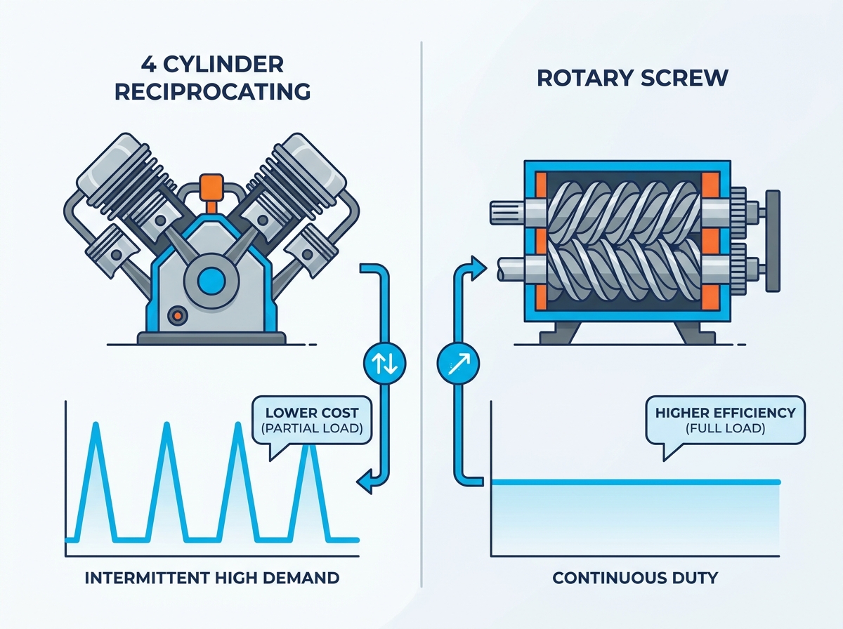
The most critical distinction between reciprocating models and rotary screw systems involves the duty cycle. Reciprocating pumps generate substantial friction. To prevent catastrophic overheating and oil breakdown, manufacturers physically limit them to a 60% to 80% duty cycle. They must turn off and cool down periodically.
Rotary screw systems utilize oil-flooded rotors designed for 100% continuous duty. They thrive when running 24 hours a day without stopping. If your facility absolutely never stops consuming air, rotary screws make sense. If your demand has natural breaks, reciprocating pumps fit better.
Evaluating energy consumption reveals stark differences under fluctuating demand. Rotary screw compressors waste significant electrical energy if left idling. Because they are designed to run constantly, dropping to partial load makes them highly inefficient. You pay for electricity even when tools sit idle.
A reciprocating pump operates on a simple start-stop mechanism. When the receiver tank hits maximum pressure, the motor shuts completely off. It consumes zero electricity until line pressure drops below the restart threshold. For highly fluctuating demands, this start-stop efficiency drastically reduces monthly utility bills.
Maintenance paradigms differ completely between the two technologies. Reciprocating pumps require frequent but highly accessible mechanical upkeep. Facility maintenance teams can easily replace air filters, swap synthetic oil, and install new reed valves or piston rings using standard hand tools.
Rotary screws require specialized interventions. You must meticulously manage complex fluid levels, separator filters, and thermal valves. When the main airend eventually requires service, you cannot rebuild it on-site. You must ship it to a specialized facility, causing longer potential downtimes.
Noise pollution matters in indoor facilities. Reciprocating pumps create a distinct, low-frequency mechanical thumping. They output higher decibel levels, often requiring dedicated compressor rooms or sound-dampening enclosures to protect worker hearing.
Rotary screw models feature fully enclosed steel cabinets lined with acoustic foam. They emit a smooth, high-frequency hum that easily blends into background factory noise. You can comfortably hold a conversation standing right next to a modern rotary screw machine.
Compressor Technology Comparison
| Feature/Metric | 4-Cylinder Reciprocating | Rotary Screw Compressor |
|---|---|---|
| Duty Cycle | 60% - 80% (requires rest periods) | 100% Continuous Flow |
| Energy Efficiency | Excellent at partial/fluctuating loads | Poor at idle; requires constant demand |
| Maintenance Needs | Frequent but simple (valves, rings, oil) | Specialized (separators, airend rebuilds) |
| Acoustic Output | Loud, low-frequency thumping | Quiet, enclosed acoustic hum |
Heavy iron moving rapidly creates massive kinetic energy. You cannot simply place these heavy-duty pumps on a wooden pallet or a thin concrete slab. You must secure them properly to a reinforced concrete foundation using heavy-duty anchor bolts.
Furthermore, you must install thick rubber anti-vibration pads under every mounting foot. Skipping this step allows intense low-frequency vibrations to transfer directly into the floor. Over time, this constant shaking causes structural fatigue in the building and shatters hard-piped airline joints.
Compressing large volumes of atmospheric air inevitably produces gallons of liquid condensate. Hot air holds moisture; as it compresses and cools inside the tank, water drops out rapidly. At industrial CFM rates, this water generation accelerates exponentially.
You must actively protect downstream pneumatic tools and machinery. Merely draining the tank daily falls short. You should pair the pump with an appropriately sized aftercooler. Additionally, install a refrigerated air dryer immediately downstream. This equipment drops the air's dew point, stripping away residual moisture before it ruins paint finishes or rusts expensive CNC valves.
Pump location dictates operational survival. Pulling in dirty, hot air guarantees a short lifecycle. High ambient temperatures degrade synthetic lubricating oils rapidly, breaking down their protective barriers. Airborne dust bakes onto hot reed valves, causing severe carbonization and eventual valve failure.
Ensure the installation room boasts massive cross-ventilation to exhaust rejected heat. If the room remains dusty, pipe the air intake filters outside the building. Pulling cool, clean outdoor air extends the physical life of internal components drastically.
Predictability keeps production running. You must plan for specific wear items. Mechanics will routinely replace intake air filters, change high-grade synthetic oil, and inspect drive belt tension. Gaskets and reed valves represent the next tier of standard replacements.
Assuming strict adherence to duty cycles and ambient temperature controls, expect many thousands of hours of reliable service. Eventually, you will perform a full top-end rebuild. Replacing pistons, rings, and honing the cylinders restores factory compression, allowing the heavy cast-iron block to serve another long lifecycle.
Never guess your facility's air requirements. Overestimating wastes capital; underestimating starves production. You need mathematical certainty before contacting vendors. Follow a strict load audit protocol to calculate your true demand.
The receiver tank acts as a massive pneumatic battery. It stores energy so the pump does not have to start every time someone pulls an air trigger. The mathematical relationship between pump output and storage capacity dictates pump cycling frequency.
A standard 120-gallon tank works well for steady, moderate usage. However, heavy burst applications drain small tanks rapidly, forcing the motor into frequent, damaging start sequences. Upgrading to a 200-gallon or larger ASME-certified tank reduces short-cycling. The pump runs longer to fill the larger volume, but rests significantly longer between cycles.
Industrial machinery introduces serious safety liabilities. Never install uncertified pressure vessels in a commercial environment. Verify the receiver tank carries an ASME (American Society of Mechanical Engineers) certification stamp, proving it passed rigorous weld and burst testing.
Confirm the pulley systems feature fully enclosed, OSHA-compliant belt guards to protect workers from rotating machinery. Finally, inspect the electrical components. Ensure the motor and magnetic starters feature UL or CSA listings. Insurance inspectors and municipal code enforcement officers actively look for these specific safety credentials.
Begin reaching out to industrial vendors once your math is solid. Look closely at warranty structures. Many brands offer a one-year warranty on the whole package, but extend coverage to three or five years on the bare pump. Read the fine print carefully.
Investigate local parts availability. Buying a cheaper imported model saves money today, but waiting three weeks for a proprietary gasket halts your entire production line. Prioritize manufacturers boasting robust domestic distribution networks and readily available top-end rebuild kits.
A multi-cylinder setup effectively bridges the massive gap between struggling light-duty pumps and overly expensive rotary screw infrastructure. By leveraging V or W configurations, these machines push exceptional volumes of air while keeping operating temperatures manageable. They handle the chaotic, burst-heavy demands of modern auto shops, fabrication yards, and woodworking facilities effortlessly.
Your final decision rests on demand mapping. If your facility requires massive air volume with natural breaks in demand, this technology remains the optimal choice. It gives you the power you need without the idle energy waste. However, if your air demand literally never stops across multiple shifts, you should pivot to rotary screw technology. Analyze your flow, size your tank correctly, and build a pneumatic infrastructure that drives revenue instead of bottlenecks.
A: A high-quality industrial pump typically lasts between 10,000 to 15,000 operational hours before needing a full top-end rebuild. This lifespan heavily depends on running the pump at lower RPMs, strictly adhering to synthetic oil change intervals, and keeping ambient room temperatures below 100°F (38°C).
A: No. Reciprocating pumps generate significant friction and heat. You must adhere to the manufacturer-specified duty cycle, which usually ranges from 60% to 80%. Running them continuously without rest periods leads to oil breakdown, valve carbonization, and catastrophic pump failure.
A: Yes. Because they utilize large 10 HP to 30 HP motors, they pull massive inrush currents during startup. They require hardwired, commercial 3-phase power and a dedicated magnetic starter to handle the load safely and prevent dangerous voltage drops.
A: Both configurations optimize airflow and thermal dissipation effectively. Your choice usually depends on vendor proprietary designs, your specific footprint constraints, and ease of maintenance access. V-blocks are generally wider, while W-blocks pack cylinders tighter for a slightly smaller footprint.